An air conditioning system leaking refrigerant is a ticking clock. Every day the leak goes unfound, the system loses cooling capacity, electric bills climb, and the compressor works harder against dropping suction pressure. A technician who can diagnose the leak in one visit instead of three saves the customer money and frees up the schedule for more jobs. The problem is that refrigerant leaks are invisible. They leave no stain, no wetness, and no trace that the naked eye can see. Electronic detectors help, but they struggle with small leaks, outdoor units in wind, and evaporator coils buried inside the air handler.
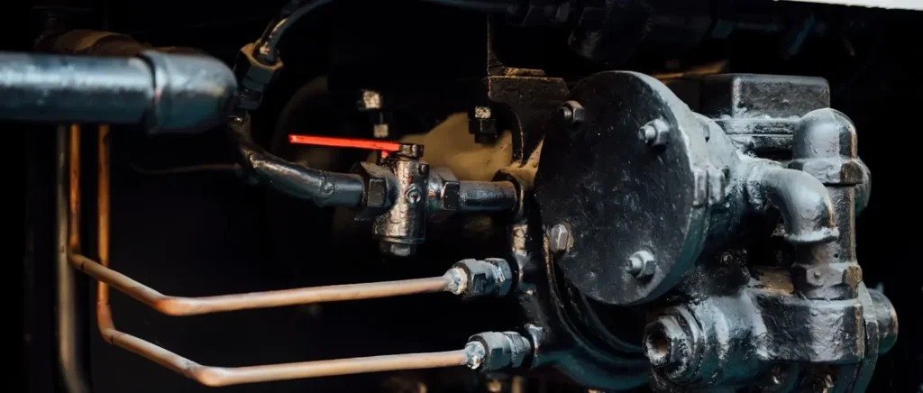
To use HVAC UV dye to spot AC leaks fast, inject the correct fluorescent dye into the system through the low-side service port, run the system for 15 to 30 minutes to circulate the dye, then scan all components with a 365 nm UV inspection lamp while wearing yellow contrast glasses. The dye will glow bright yellow-green at every leak point, from the smallest pinhole in an evaporator coil to a hairline crack in a condenser U-bend.
This guide covers every step of the process, from selecting the right dye and tools to locating leaks on specific AC components.
What tools and materials do you need to use HVAC UV dye?
A complete HVAC UV dye leak detection kit requires four items: the correct fluorescent dye for the system oil type, a dye injector, a 365 nm UV inspection lamp, and yellow contrast glasses. Optional but useful additions include a refrigerant manifold gauge set, a clean rag, and a paint pen for marking leak points.
The most common mistake is starting with the wrong dye. The dye must match the system oil type. R-410A and R-134a systems use POE oil and need POE-based dye. R-22 systems use mineral or alkylbenzene oil and need mineral oil-based dye. UV dye for HVACR products are labeled clearly by oil type. A mineral oil dye in a POE system will not dissolve properly and can cause oil return problems.
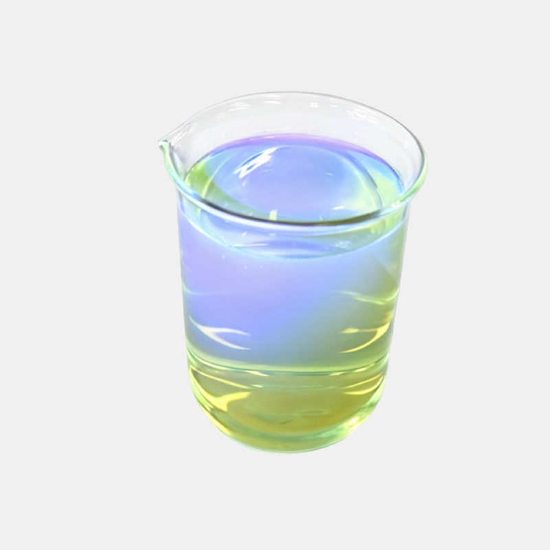
The dye injector threads onto the low-side service port and uses system suction to pull dye in. Pre-filled injectors are faster and eliminate air contamination risk. Reusable injectors save money but require cleaning between jobs to prevent cross-contamination.
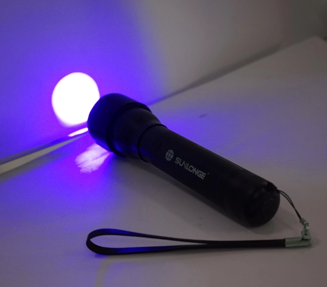
The lamp is where quality matters most. A 365 nm lamp with a proper bandpass filter excites dye at its peak absorption wavelength. A 395 nm lamp, common in budget lights, produces substantially less fluorescence on the same dye stain. A leak visible from several feet away under 365 nm light can disappear under 395 nm light in anything but total darkness. A quality UV leak detection light pays for itself by catching leaks cheaper lamps miss.
Yellow contrast glasses block residual UV-A and filter ambient blue light. In a well-lit mechanical room or on a sunny rooftop, the glasses are not optional. Ambient light washes out fluorescence without them.
| Tool | Purpose | Key selection factor |
|---|---|---|
| Fluorescent UV dye | Tracer that escapes at leak points | Oil type match (POE, mineral, PAG) |
| Dye injector | Delivers dye into the system | Reusable vs. pre-filled |
| 365 nm UV lamp | Excites dye to fluoresce | Wavelength and filter quality |
| Yellow contrast glasses | Blocks ambient light and UV-A | Must match lamp wavelength |
How do you inject HVAC UV dye into an AC system?
Inject HVAC UV dye through the low-side service port while the compressor is running. Attach the dye injector to the suction line service valve, open the injector valve slowly, and let system suction pull the dye in over 15 to 30 seconds. Never inject dye into the high-side port because the high pressure will push dye backward into the injector.
Before injection: check the system
Connect manifold gauges and record static pressure. A completely empty system cannot circulate dye. If the compressor is off on a low-pressure safety, reset or jumper the switch temporarily to get it running. Dye circulates with compressor oil. No compressor means no circulation. Confirm the compressor is actually running by checking amp draw and pressure differential.
The injection process
Shake the dye bottle thoroughly. Fluorescent dye settles over time, and the concentrate must be evenly mixed with the carrier. If the dye was stored in a hot truck, let it cool first.
Attach the injector to the low-side service port. Open the low-side manifold valve. Slowly open the injector valve and watch the dye flow. Suction pressure of 60 to 80 psig on a running R-410A system pulls dye in rapidly. If dye does not flow, the injector may be clogged, the service valve core may not be depressed, or suction pressure may be too low.
A standard dose is 1 to 2 ounces for systems up to 10 tons. Larger systems need proportionally more dye. Follow the manufacturer’s dose recommendation on the bottle.
After injection
Close the injector valve, remove it from the service port, and wipe any spilled dye from the valve body. Spilled dye on the outside of the port will fluoresce and look like a leak. Clean thoroughly to avoid chasing a false positive.
Label the system. Write the date, dye type, and dose inside the electrical panel cover. The next technician knows dye is present and avoids adding a second dose.
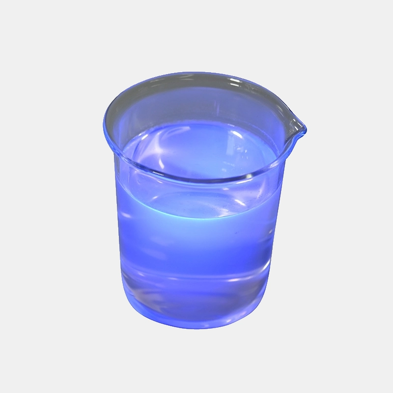
Fluorescent UV leak detection dyes come in liquid, cartridge, and syringe formats. The injection process is the same. The key difference is convenience and measuring accuracy. A pre-measured cartridge removes the guesswork and is faster on a busy call.
How long should the dye circulate before inspection?
Run the system for 15 to 30 minutes after dye injection before beginning the UV lamp inspection. Residential split systems with short line sets need at least 15 minutes. Commercial systems with long refrigerant lines, large receivers, or multiple evaporators should circulate for 30 minutes or longer.
The dye circulates dissolved in the compressor oil. In a typical 3-ton residential split system with 50 feet of line set, the oil makes a complete loop in roughly 5 to 10 minutes. Running for 15 minutes gives at least one full cycle, ensuring dye has passed through the condenser, liquid line, metering device, evaporator, and suction line.
Circulation time matters for slow leaks. A leak losing only a few ounces per year deposits a microscopic amount of dye each cycle. Running for 30 minutes instead of the minimum 15 can make a slow leak visible that would be missed with a shorter run time.
During circulation, use the time productively: check the air filter, clean the condenser coil, measure temperature split, and verify airflow. When circulation is up, the diagnostic data is already collected and inspection can begin.
How to spot AC leaks with a UV inspection lamp
Put on yellow contrast glasses, turn on the 365 nm UV lamp, and scan every component in the refrigerant path from the compressor to the evaporator. A leak appears as a bright yellow-green glow at the exact point where refrigerant escapes. This is the core of UV fluorescent leak detection, and it works on any system regardless of refrigerant type or system size.
Scanning technique
Start at the outdoor unit. Scan the compressor shell at all weld seams and around the terminal block. Compressor terminal leaks are common on older units and appear as a ring of fluorescence around the terminal pins. Then scan the service valves. Dye around the valve stem packing nut indicates a stem leak. Dye on the Schrader valve core indicates a core leak.
Scan the condenser coil face in a grid pattern, top to bottom, left to right. Move the lamp slowly. Hold it 6 to 12 inches from the surface and move at roughly 1 foot per second. Any yellow-green spot that stays in place when you move the lamp is a dye deposit. Dust, pollen, and some thread sealants also fluoresce but look duller, whiter, or bluish compared to the pure bright yellow-green of dye.
Scan the line set if accessible. Pay attention to points where the line set passes through a wall, floor, or roof penetration. Vibration at these points causes rub-through leaks. A long dye trail on the insulation surface points to a leak upstream where refrigerant is escaping and being blown along the pipe by wind or fan airflow.
Indoor inspection
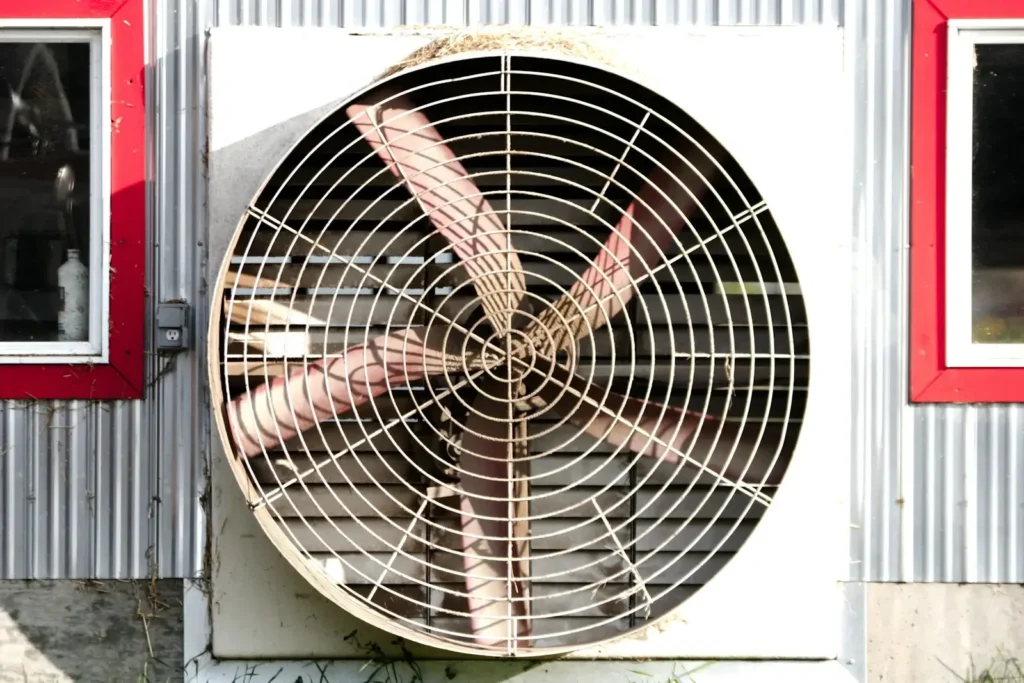
Remove the air handler access panel and scan the evaporator coil. Evaporator leaks are the hardest to find because the coil sits inside a dark cabinet with poor access. A leak detection lamp with a flexible head or right-angle design makes it easier to get light onto the coil face.
Scan the U-bends at the coil end first. These are the most common leak points on evaporator coils because of formicary corrosion. Then scan the tube sheet where tubes enter the fins. Scan the distributor tubes and the suction line connection. For multi-row slab coils, scan between rows as deep as the lamp reaches.
If the evaporator is leaking, dye appears in the condensate. Collect a sample of drain water in a clear container and shine the UV lamp through it. A uniform yellow-green glow confirms an evaporator leak. This provides a quick yes-or-no answer without full coil disassembly.
What are the most common AC leak points found with UV dye?
The most common AC refrigerant leak points are evaporator coil U-bends and tube sheets (formicary corrosion), condenser coil tube-to-fin joints, compressor terminal blocks, Schrader valve cores, service valve stems, brazed joints on the liquid line, and line set rub-through points at wall or roof penetrations.
Evaporator coil leaks
Formicary corrosion is the leading cause of evaporator coil failure. It is caused by formic and acetic acids in indoor air attacking the copper tubing, creating pinholes invisible to the naked eye. UV dye accumulates around each pinhole and fluoresces as a bright dot. An electronic detector often cannot isolate individual pinholes on a densely finned coil.
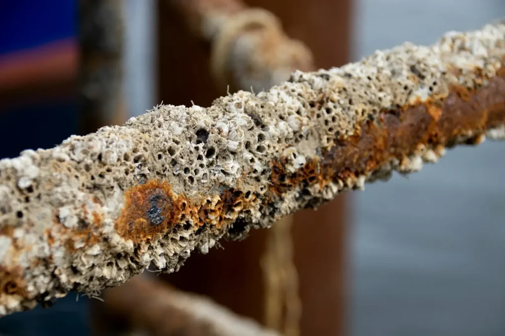
The tube sheet, where copper tubes pass through the aluminum end plate, is another high-frequency leak point. Thermal cycling between the copper and aluminum causes the tubing to wear thin. Leaks at the tube sheet appear as a line of dye along the joint.
Condenser coil leaks
Condenser leaks are most common at tube-to-fin joints and U-bends. Vibration, thermal cycling, and weather exposure cause fatigue. A rooftop unit exposed to rain, snow, and sun develops leaks faster than one under a canopy. Hail damage is another source: small dents in aluminum fins may hide a cracked tube underneath.
Service valve and Schrader core leaks
Schrader cores are the most overlooked leak point. The tiny O-ring inside degrades over time. A drop of dye around the Schrader port with the cap off confirms the leak. The fix is a ten-second core replacement costing less than a dollar. Service valve stem packing leaks show as a ring of fluorescence around the stem. Tightening the packing nut stops most of them.
Brazed joints and line sets
Every braze joint is a potential leak point. A joint that looks clean may have incomplete penetration or a hidden pinhole. Years of vibration can open a pinhole that passed pressure test on installation day.
In automotive HVAC systems, the leak distribution is similar but with added challenges: the evaporator is inside the dashboard, the condenser sits behind the grille, and the compressor shaft seal is a wear item. UV dye is the standard diagnostic method for these access-challenged points.
How does UV dye compare to other leak detection methods?
UV dye detection outperforms electronic sniffers and bubble solutions for small and intermittent leaks, leaks in windy environments, and evaporator coil leaks that are physically inaccessible.
| Method | Best for | Limitation | Dye advantage |
|---|---|---|---|
| UV dye + lamp | Small/intermittent leaks, evaporator leaks, outdoor units | Requires injection and circulation time | Permanent mark, wind-proof, coil access |
| Electronic sniffer | Quick scan of a fully charged system | Misses small leaks, fails in wind | Dye finds leaks below sniffer threshold |
| Bubble solution | Large obvious leaks, confirming joints | Misses pinholes, cannot access enclosed components | Dye fluoresces regardless of leak size |
| Nitrogen pressure test | Confirming system integrity | Does not locate leaks, requires recovery | Dye locates exact point without recovery |
Electronic detectors have a sensitivity threshold. A leak below that threshold will not trigger an alarm. The same leak given enough run time deposits enough dye to become visible. This is why dye is the tool of last resort for intermittent leaks other methods cannot confirm.
Wind disperses escaping refrigerant before a sniffer can sample it. An outdoor unit on a windy day, a rooftop unit in any weather, or even a condenser with strong fan airflow will give false negatives on an electronic detector. Dye on the surface is unaffected by airflow.
For evaporator coil leaks, dye and nitrogen pressure testing are the only two methods that give a reliable diagnosis without cutting the coil out. Electronic detectors cannot reach the coil surface in a tightly packed A-coil or N-coil. Dye in the condensate provides the same diagnosis non-invasively.
The full leak detection solutionsspectrum includes each method. Experienced technicians use multiple methods on the same call: a quick sniffer pass for large leaks, then dye injection if the system is losing charge but the sniffer finds nothing.
How to choose the right dye and avoid common mistakes
To choose UV leak detection dye correctly, match the dye carrier oil to the system oil type, use the manufacturer’s recommended dose, verify the dye is rated for the system’s operating temperature range, and check its compatibility with the specific refrigerant. The most common mistakes are oil type mismatches, overdosing, and using expired dye that has lost its fluorescence.
| Mistake | Consequence | Prevention |
|---|---|---|
| Wrong oil carrier | Dye does not circulate, possible compressor damage | Read system nameplate for oil type |
| Overdosing | Dye precipitation, clogged metering device | Follow dose chart on bottle |
| Expired or heat-damaged dye | Weak or no fluorescence, false negatives | Check date, store below 120 F |
| Skipping circulation time | False negatives on distant components | Run at least 15 minutes |
| No contrast glasses | Missed leaks in ambient light | Always wear yellow glasses |
| Spilled dye not cleaned | False positives at injection point | Wipe service port after injection |
Oil type matching is the single most important decision. A POE-based dye in a mineral oil system will not dissolve properly. A mineral oil dye in a POE system may not return to the compressor. The system nameplate identifies the refrigerant, which identifies the oil type. R-410A and R-134a use POE. R-22 uses mineral or alkylbenzene.
Dye concentration matters. The standard dose produces 0.5 to 2 percent dye in the circulating oil. More dye does not make leaks brighter. It increases the risk of dye precipitating as solid particles that can clog the metering device.
Expired dye is a hidden problem. Fluorescent molecules degrade over time, especially in heat. A bottle sitting in a service truck through two summers may have lost significant fluorescence. Test a drop on a white surface under the UV lamp before injecting. If it does not glow brightly, replace it.
Choose UV leak detection dye for the specific application. Systems with marginal oil return, low-temperature refrigeration, and large chillers benefit from a dedicated dye matched to exact operating conditions.
Conclusion
UV dye turns invisible refrigerant leaks into a visual diagnosis. Inject dye, circulate, scan with a UV lamp, and mark the leaks. The method is simple. The value is in the details: the right dye for the oil type, a quality 365 nm lamp with proper filtration, contrast glasses, and methodical scanning.
A technician who masters UV dye can diagnose an evaporator coil leak in ten minutes that would take an hour with an electronic detector. On a rooftop unit in the wind, dye works when the sniffer does not. On a slow leak losing a pound per year, dye accumulates continuously and gets brighter with time.
The dye costs a few dollars per dose. The lamp is purchased once. The return is faster diagnosis, fewer callbacks, and a method that works regardless of wind, leak size, or component accessibility.
FAQ
Can UV dye be used in a system that already has dye from a previous service?
Yes. Dye remains stable for the life of the system. When you encounter a unit with existing dye, skip the injection step and go directly to scanning. If the old dye appears dimmer than expected, a fresh dose can be added to restore bright fluorescence.
Does UV dye work in heat pump systems in heating mode?
Yes. The dye circulates with the oil regardless of flow direction. In heating mode, scan the indoor coil (now the high-pressure side) and the outdoor coil (now the low-pressure side). Dye accumulates at the leak regardless of which side of the reversing valve the leak is on.
How do you remove UV dye from the system?
Dye removal requires a full system flush with a solvent designed for HVAC use, followed by evacuation, a new filter-drier, and a fresh refrigerant charge. In practice, removal is rarely necessary. The dye is chemically inert and does not affect system performance, so it is usually left in place permanently.