Every summer, auto repair shops see the same pattern. A customer rolls in with an AC that blows warm air. The technician hooks up the gauges, confirms low refrigerant pressure, and now faces the real problem. Finding the leak. Modern car AC systems have dozens of connection points, seals, hoses, and components, any one of which can develop a pinhole that bleeds refrigerant over weeks or months. The leak itself is invisible. Refrigerant is colorless and odorless at atmospheric pressure, and it escapes as a gas that leaves no wet spot or stain.
To find a car AC refrigerant leak with UV dye, inject fluorescent dye into the AC system, run the compressor for 10 to 15 minutes to circulate the dye through the entire refrigerant loop, then scan all common leak points with a 365 nm UV inspection lamp. The dye will glow bright yellow-green at every point where refrigerant has escaped, including the compressor shaft seal, condenser face, hose crimps, service port Schrader valves, evaporator drain, and O-ring joints.
This guide walks through the specific points where car AC systems leak most often, the step-by-step diagnosis process with UV dye, and the tools that make the job faster and more accurate.
What are the most common car AC refrigerant leak points?
The most common car AC refrigerant leak points are the compressor shaft seal and case O-rings, the condenser face and end tanks, hose crimp connections, service port Schrader valves, the evaporator core, and O-ring joints at every component connection. Together these account for more than 90 percent of all car AC leaks seen in repair shops.
Knowing where to look before you start scanning cuts diagnosis time in half. A technician who checks every inch of the system from scratch wastes 30 minutes on a job that should take 10. A technician who goes straight to the high-probability points finds the leak on the second or third scan.
Compressor shaft seal and case O-rings
The compressor is the most common leak source. The shaft seal where the clutch shaft enters the compressor body must hold refrigerant at pressures exceeding 250 psi. Heat cycling degrades the seal lip over time. Case O-rings between compressor housing sections fail in the same way, showing dye stains along the housing seam.
The compressor sits low on most engines, so dye often runs downward and pools on the subframe. If you see dye on the shield but not on the compressor, the leak is at the compressor and has dripped down.
Condenser face and end tanks
The condenser sits in front of the radiator and takes road debris at highway speed. A stone that bends a few fins can also puncture a refrigerant tube. These punctures are hard to find without dye because refrigerant escapes as a gas jet that leaves no residue.
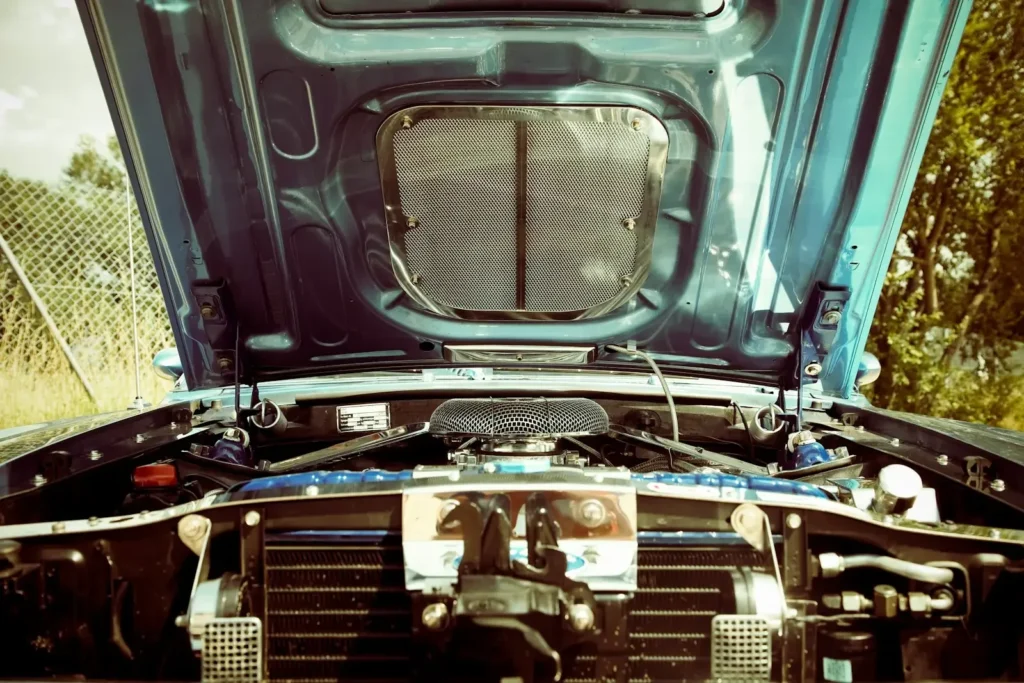
Condenser end tanks with aluminum crimp-to-core construction develop leaks at the gasket seal from repeated thermal cycling. The leak starts as a slow seep. Scan the condenser face from the grille opening, focusing on bent fin areas and end tank seams.
Hose crimp connections
Every rubber-to-metal crimp on the AC hoses can leak. The crimp collar compresses the hose around a barbed fitting. After years of heat and pressure cycling, the rubber liner takes a compression set and loses its grip. Refrigerant seeps between the liner and fitting, traveling along the reinforcement braid to exit at the end of the crimp.
Dye at the end of a crimp collar means the hose assembly needs replacement. The actual leak is inside the hose under the crimp. Tightening will not fix it.
Service port Schrader valves
The high and low side service ports use a Schrader valve core with a small rubber gasket that wears with every gauge set connection. A valve that has seen 50 service cycles over 10 years has likely lost enough seal material to leak.
The plastic cap provides a secondary seal. If the cap is missing and the system is low, check the Schrader valve first. Dye pools inside the port cavity and may not be visible until the cap is removed.
Evaporator core
The evaporator is the most expensive leak to repair because it lives inside the HVAC case behind the dashboard. Access requires removing the dash, a 6 to 10 hour job on most vehicles. Correct diagnosis before committing is critical.
Dye in the condensate drain water is the telltale sign. Inject dye, run the AC for 15 to 20 minutes to build condensation, then scan the evaporator drain outlet under the vehicle. If dye is present in the drain water, the evaporator is leaking. If the drain water is clear but refrigerant loss continues, the leak could be too slow for visible dye concentration. Retest after a full week of driving.
O-ring joints at component connections
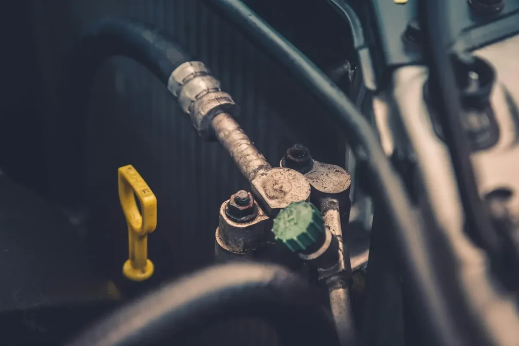
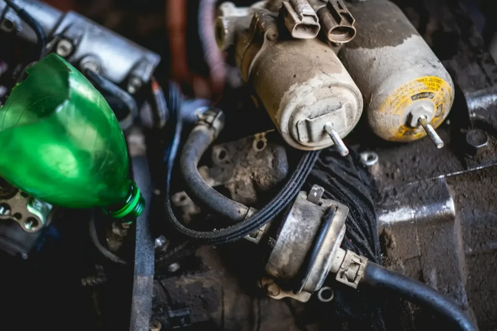
Every component in the AC loop connects to the next with a bolted flange and an O-ring seal. These are the accumulator or receiver-drier connections, the TXV or orifice tube connections, the line set connections at the compressor, condenser, and evaporator, and the pressure sensor and pressure switch ports.
O-ring leaks are usually caused by age, heat, and oil exposure. The O-ring material hardens, loses elasticity, and can no longer conform to the groove under system pressure. On older vehicles, replacing every O-ring in the system as part of a major AC repair is standard practice.
Each of these leak points is a known failure location in automotive HVAC systems across all vehicle makes and models. The failure rates vary by vehicle, but the locations are universal.
Why does UV dye outperform other leak detection methods?
UV dye detection finds leaks that electronic sniffers and bubble solutions miss because the dye physically deposits at the leak site and remains visible for hours or days after the refrigerant has dissipated. A sniffer can only detect refrigerant vapor that is actively escaping and present in the air at the probe tip at the moment of testing.
An electronic leak detector works by sampling the air around a suspected leak point and measuring the concentration of refrigerant vapor. The detector beeps or lights up when the concentration crosses a threshold. This works for large leaks in accessible locations. It fails for small leaks where the refrigerant concentration at the probe tip is below the detector’s sensitivity. It also fails in windy conditions, where escaping refrigerant is dispersed before the detector can sample it.
Bubble solutions, the oldest method, require applying a soap solution to every joint and watching for bubble formation. A leak that produces one bubble every 30 seconds is easy to miss. The technician needs direct line of sight to every test point, which is impossible inside an evaporator case or behind a compressor.
UV fluorescent leak detection dye solves both problems. The dye is carried through the entire system by the refrigerant and compressor oil. It exits at the leak point and stays there. The technician can return to the vehicle hours or days later and the dye will still fluoresce under a UV lamp. Wind does not blow it away. Low concentration does not prevent detection because even a microscopic amount of dye produces visible fluorescence.
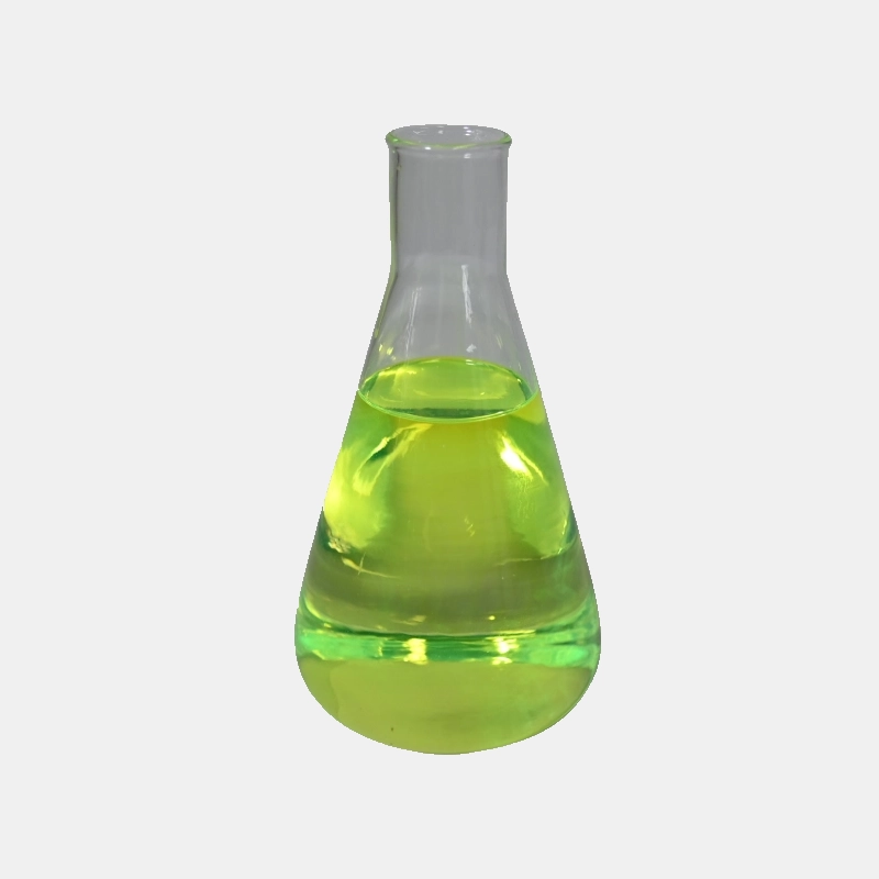
Fluorescent UV leak detection dyes are chemically stable, non-corrosive, and compatible with all common refrigerants (R-134a, R-1234yf, R-12) and compressor oils (PAG, POE, mineral). The dye does not react with the refrigerant, degrade the oil, or clog the orifice tube or expansion valve. Once injected, it remains in the system and continues to mark any future leaks, which makes follow-up diagnosis after a repair straightforward.
| Method | Finds small leaks | Works in wind | Works on evaporator | Cost per test |
|---|---|---|---|---|
| UV dye + inspection lamp | Yes | Yes | Yes (via drain) | $2-5 |
| Electronic sniffer | No (below threshold) | No | No (inaccessible) | $0 (reusable tool) |
| Bubble solution | No (slow leaks) | No | No | $1 |
| Nitrogen pressure test | Yes (if large enough) | Yes (gauges) | Yes (gauges) | $5-10 |
How to inject UV dye into a car AC system
Inject UV dye into the low-side service port using a dedicated dye injector or a dye cartridge that attaches to the manifold gauge set. The correct dose is typically 0.25 to 0.5 fluid ounces per vehicle, which is one standard syringe or cartridge. Never exceed the recommended dose. Too much dye can foul the desiccant in the accumulator or receiver-drier.
Step 1: Verify system pressure
Before injecting anything, connect a manifold gauge set and check static pressure with the engine off. If the system is completely empty (zero pressure), do not inject dye. Recover any remaining refrigerant, pull a vacuum to check for gross leaks, and repair them first. UV dye injection requires at least enough refrigerant charge to circulate the dye. A system with 10 to 20 psi static pressure can usually pull in the dye during compressor operation.
Step 2: Select the dye type
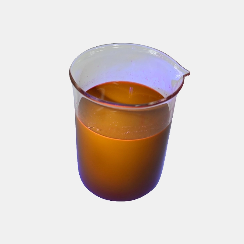
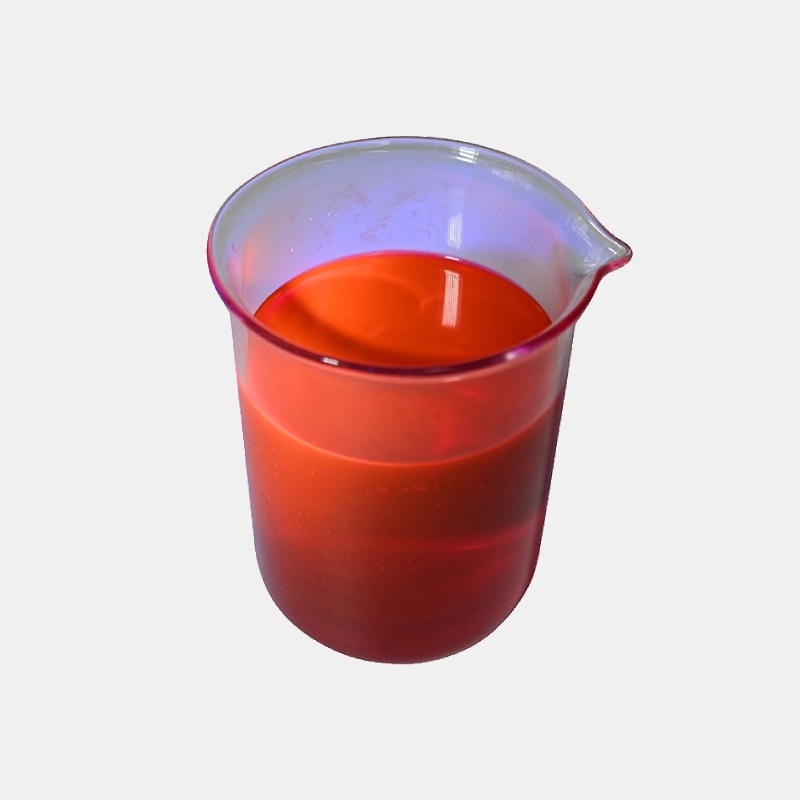
UV dye for HVACR systems comes in three carrier formats: pure dye concentrate, dye suspended in compressor oil, and dye in a solvent carrier. Pure concentrate is the most common for automotive use. It mixes with the existing compressor oil and circulates with it. Oil-based dye is used when the system is being refilled with fresh oil, such as after a compressor replacement. Solvent-based dye is for systems that have already been contaminated with stop-leak or other additives.
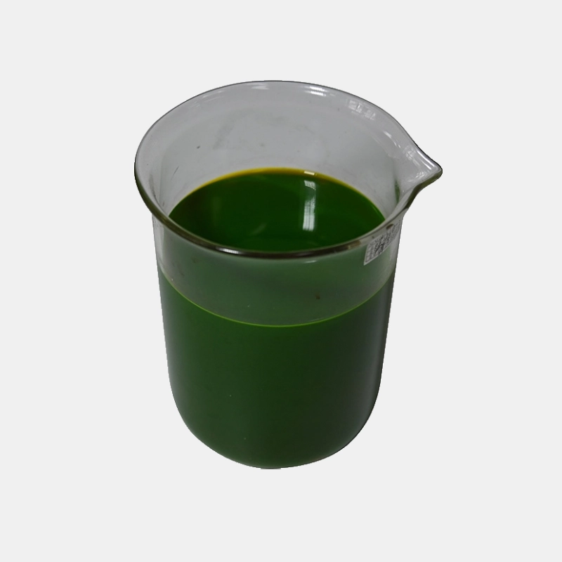
Match the dye to the refrigerant type. R-134a systems use PAG oil. R-1234yf systems use a specific POE oil. The dye must be labeled as compatible with the specific refrigerant and oil combination in the vehicle.
Step 3: Inject the dye
With the engine running and AC set to maximum cool, connect the dye injector to the low-side service port. The low side runs at 25 to 45 psi during operation, which is low enough for most injectors to push against. Open the injector valve slowly and let system suction pull the dye in. This takes 30 to 60 seconds for a full dose. Close the valve, disconnect the injector, and replace the service port cap.
Step 4: Circulate the dye
Run the AC for at least 10 to 15 minutes with the blower on high and the temperature set to maximum cool. This ensures the dye travels through the compressor, condenser, receiver-drier or accumulator, expansion device, evaporator, and back to the compressor. Cycle the AC on and off two or three times during this period to create pressure changes that push dye through any leak paths.
Step 5: Inspect with a UV lamp
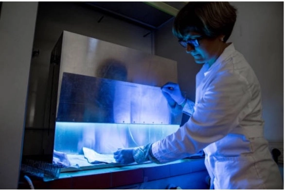
Put on yellow contrast glasses and scan the system with a UV leak detection light. Start at the compressor and work methodically toward the evaporator. Check every joint, crimp, seal, and component face. Pay attention to the underside of hoses and components where dye may have run downward.
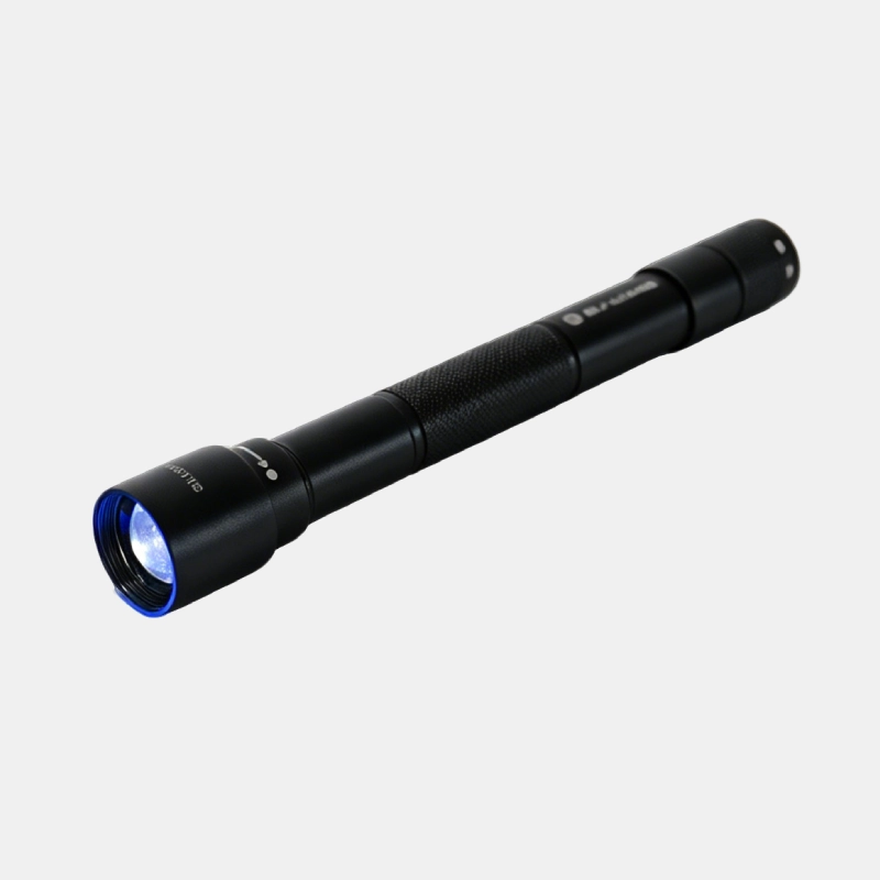
For large leaks, dye will appear within minutes of injection. For slow seeps, dye accumulation may take hours or days of normal driving to become visible. If no leak is found during the initial inspection, ask the customer to drive the vehicle for a week and return for a follow-up scan.
How to find leak points with a UV inspection lamp
Use a 365 nm UV inspection lamp with yellow contrast glasses to scan every component in the refrigerant loop. The dye fluoresces bright yellow-green at leak points. Start at the compressor, follow the high-side line to the condenser, then the liquid line to the evaporator, and finally the low-side return line.
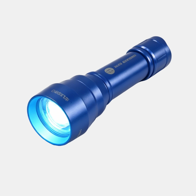
Hold the lamp 6 to 12 inches from the target surface with the beam perpendicular to the area. Shallow angles reflect UV light and make fluorescence harder to see. Work in sequence along the refrigerant path to avoid skipping components. Check both sides of every hose, as dye often runs along the underside and pools in low spots.
For the evaporator drain tube, point the UV lamp directly into the drain opening under the vehicle. Yellow-green fluorescence in the drain water confirms an evaporator leak. No dye in the drain after multiple drive cycles makes an evaporator leak unlikely.
How to diagnose different types of AC leaks based on dye patterns
The dye pattern at a leak point reveals the leak type, severity, and sometimes the root cause. A single bright spot indicates a pinhole. A circumferential stain around a hose fitting suggests a crimp failure. Dye running down a vertical surface points to a leak above. Multiple small spots clustered together suggest porous metal or a cracked weld.
Understanding dye patterns turns a simple leak detection exercise into a automotive AC diagnosticsprocess that identifies the root cause, not just the location.
Pinhole leaks
A single bright dot of dye, often less than 1 mm in diameter, indicates a pinhole. These are usually caused by corrosion on aluminum tubing or by a stone strike on the condenser. Pinhole leaks are slow. They can take weeks to drop the charge below the low-pressure cutoff. Repair is straightforward: replace the affected component.
Crimp joint leaks
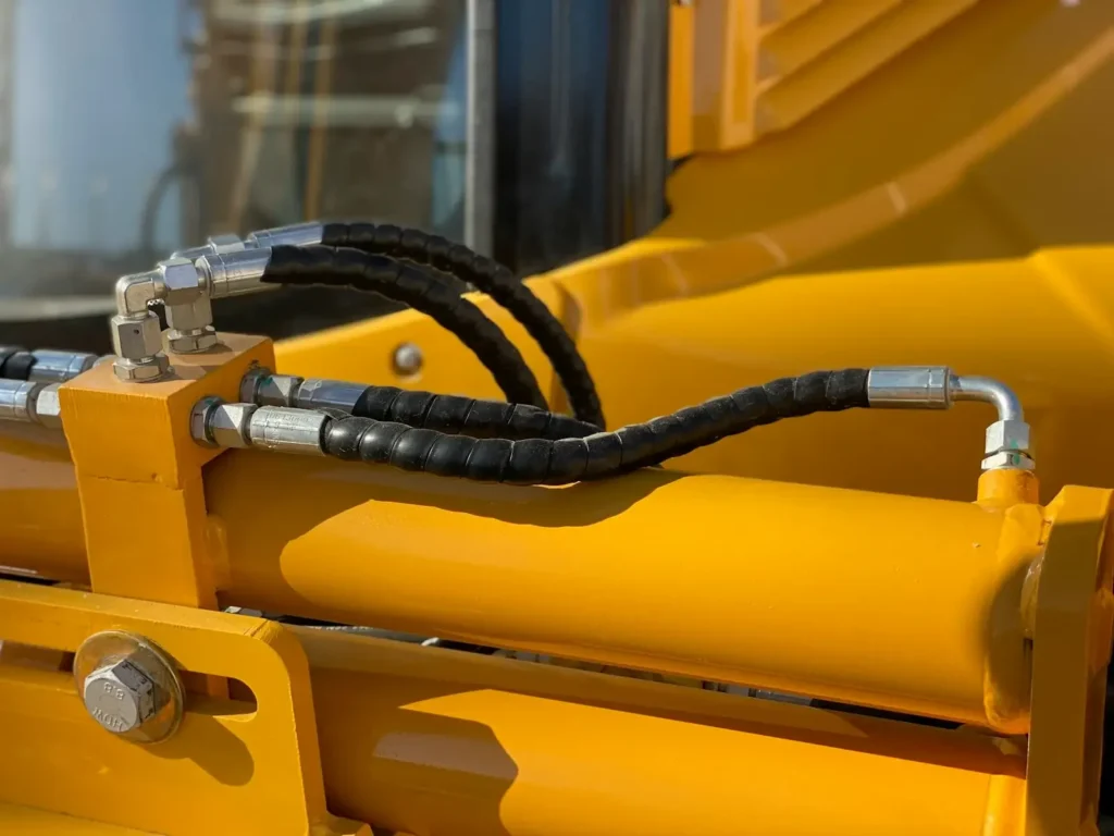
Dye that forms a ring or collar around the end of a hose crimp indicates a crimp joint failure. The rubber inner liner has lost its seal against the barbed fitting. The entire hose assembly should be replaced. Attempting to tighten a crimp joint will not restore the seal and may damage the fitting.
Seepage leaks
A faint, diffuse dye stain spread over a larger area indicates seepage. This is common at O-ring joints and gasketed connections where the seal material has hardened. The leak rate is very slow, sometimes less than an ounce of refrigerant per year. Seepage leaks are often found during routine AC service and may not cause a noticeable performance drop.
Compressor seal leaks
Dye concentrated around the compressor clutch or pulley area, often thrown in a radial pattern by centrifugal force, indicates a shaft seal leak. The dye follows the spinning shaft and sprays outward. The clutch face itself may be clean because the dye is thrown outward before it reaches the clutch. Check behind the clutch and around the compressor nose.
Multiple leak points
If you find multiple dye traces scattered across the system, the most likely explanation is that the dye was injected to find a previous leak that was repaired, the old dye was not flushed out, and a new leak has developed somewhere else. In this case, clean all the old dye traces with solvent, re-inject fresh dye, and retest. The new leak will produce the only fresh dye trace.
For shops that handle high volumes of AC work, establishing a systematic approach to leak detection solutions pays off in reduced diagnosis time and fewer misdiagnosed repairs. The cost of a dye kit and UV lamp is recovered in the first two or three jobs that would otherwise require expensive trial-and-error part replacement.
What tools and equipment are needed for UV dye leak detection?
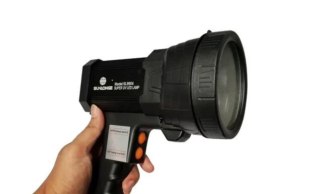
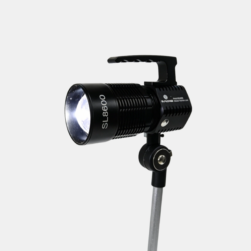
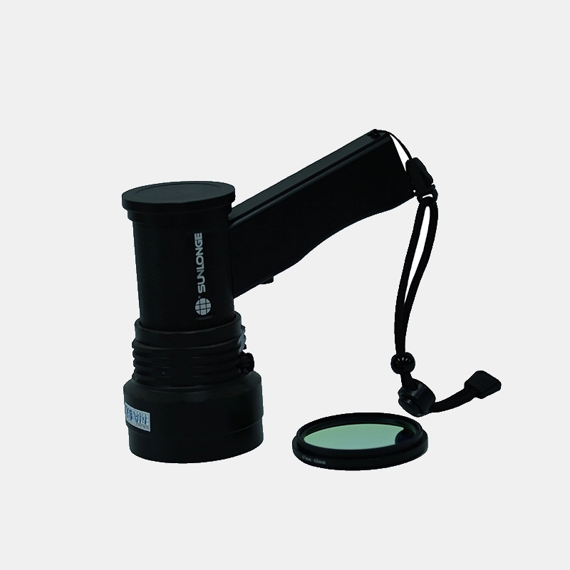
A complete UV dye leak detection kit consists of a 365 nm UV inspection lamp, yellow contrast glasses, fluorescent dye compatible with the vehicle’s refrigerant and oil type, a dye injector or cartridge adapter, and a manifold gauge set for system pressure verification.
The UV inspection lamp
A 365 nm wavelength LED with a glass filter is the minimum for professional use. Quality lamps cost $80 to $150 and last 3 to 5 years. Rechargeable lithium battery power is essential. A lamp on alkaline batteries dims after 20 minutes and produces misleading results.
Contrast glasses
Yellow contrast glasses block reflected UV-A and filter ambient blue light so fluorescence stands out. Glasses with only a yellow tint without UV blocking are cosmetic.
Dye and injector
Dye must be labeled for the specific refrigerant (R-134a, R-1234yf). The carrier oil must match the system oil type. Syringe injectors are cheaper and simpler. Cartridge systems are faster for multiple vehicles.
Manifold gauge set
A gauge set verifies system pressure before injection and monitors operating pressures during circulation. The gauges also identify non-leak problems such as a restricted orifice tube or failing compressor.
Selecting a reliable supplier matters for shops using dye kits in volume. Analysis of leak detection dye manufacturers shows substantial differences in dye concentration, filter quality, and lamp output between suppliers.
Conclusion
Car AC leak diagnosis does not need to be a guessing game. The leak points are predictable, the dye method is proven, and the process is repeatable. Every technician who works on automotive AC should know the six common leak locations by heart: compressor seals, condenser face and end tanks, hose crimps, service port valves, evaporator core, and O-ring joints. UV dye reveals all of them.
A complete diagnosis takes roughly 20 minutes from hood open to leak identified. The dye stays in the system after the repair and marks any future leaks. The tools fit in a drawer and pay for themselves in a week. For the technician, it means fewer comebacks and more confident repair recommendations. For the customer, it means a car that stays cold all summer.
FAQ
Can UV dye damage my car’s AC system?
No. UV dye formulated for automotive AC systems is chemically inert and compatible with all common refrigerants (R-134a, R-1234yf) and compressor oils (PAG, POE). The dye does not react with system components, clog expansion valves, or degrade seals. The only risk is overdosing. More than 0.5 fluid ounces of dye in a passenger car system can saturate the desiccant in the accumulator or receiver-drier, reducing its ability to absorb moisture. Follow the dose instructions on the dye packaging and do not add extra “just to be sure.”
How long does UV dye stay visible in the AC system after injection?
UV dye remains in the system indefinitely until it is flushed out. After a repair is completed and the system is recharged, the residual dye continues to circulate and will mark any future leaks. This is an advantage. A car that had dye injected two years ago and returns with a new leak still has dye in the system. The technician can go straight to the UV lamp without re-injecting. The dye does degrade very slowly over years of UV exposure on external surfaces, so a leak that was marked two years ago may have faded. But the dye inside the sealed system remains stable.
Why does my car AC still lose refrigerant after a dye test found no leak?
Three possibilities. First, the leak may be in the evaporator and the dye concentration in the condensate is too low to see. Drive the car for a full week and retest the evaporator drain. Second, the leak may only occur under specific conditions, such as high RPM or high ambient temperature, that were not replicated during the test. Ask the customer about the conditions when the AC stops working. Third, the system may have been repaired previously without flushing out the old dye, and the technician mistook old dye traces for active leaks. Clean the system, re-inject fresh dye, and retest.